Shielding for EMC: theory, apertures, seams and cables
How electromagnetic shielding works (reflection, absorption, skin depth), why apertures and seams dominate, gaskets, cable shields and shielded rooms.
A shield is a conductive barrier that reduces the field that passes from one region to another. It works for emissions (keeping fields in) and for immunity (keeping fields out). Its performance is the shielding effectiveness (SE), expressed in dB.
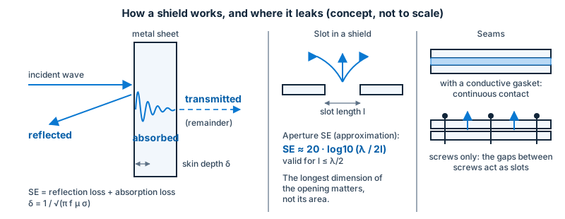
How a shield works
Three effects add up, in dB:
- Reflection loss (R): energy is reflected at the surface because of the impedance mismatch between the field and the metal. It is large for electric fields and plane waves, and small for low-frequency magnetic fields.
- Absorption loss (A): energy is absorbed as the field penetrates the metal and induces currents. Absorption depends on the thickness relative to the skin depth (δ): A in dB is about 8.7 × t/δ, where t is the thickness.
- Multiple reflection correction (B): a correction that matters only for thin shields at low frequency.
Skin depth falls with frequency and depends on the material. For copper it is about 66 µm at 1 MHz and 6.6 µm at 100 MHz, so even thin copper films shield well at high frequencies, if they are continuous.

Low-frequency magnetic fields
At 50/60 Hz and in the audio range, reflection is small and the skin depth of copper and aluminium is several millimetres, so these metals are poor magnetic shields. High-permeability materials (mu-metal, certain steels) redirect the field through the shield material; they need care in design (saturation, mechanical stress, joints).
Apertures and seams decide
In practice a shield is limited by its openings, not by the material. A slot or a seam leaks like a slot antenna: its leakage depends on its longest dimension, l. As a first estimate (textbook formula) the shielding effectiveness of an aperture is about 20·log₁₀(λ / 2l) dB when l is smaller than λ/2. A 100 mm slot gives roughly 20 dB at 150 MHz, but almost nothing at 1.5 GHz.
Remedies:
- make seams short and continuous with overlapping, bonded flanges or many closely spaced screws or fasteners;
- use conductive gaskets (mesh, fingerstock, conductive elastomer, conductive fabric) with enough compression and clean surfaces;
- break up long slots into small holes;
- ventilate through honeycomb (waveguide-below-cut-off) vents, whose depth gives high attenuation well below the cut-off frequency;
- cover displays with conductive-coated glass or mesh windows.
Penetrations: the weak points
Every conductor that crosses the shield can carry noise through it. Treat them at the boundary:
- Power and signal lines: filters bonded to the shield wall (see Filtering for EMC);
- Connectors: shielded connectors with 360° contact to the enclosure;
- Cable shields: terminated to the enclosure over 360° rather than by a pigtail;
- Fibre optics through waveguide-below-cutoff tubes, pipes through bonded collars.
Cable shields
A cable shield works through its transfer impedance (how much of the current on the outside of the shield appears as a voltage on the inside). Braided shields perform well at low and medium frequencies; foil shields at higher frequencies; combinations (foil plus braid) are common. A shield must be terminated at the connector with a low-impedance, 360° connection: a 5 cm pigtail adds roughly 50 nH and cancels much of the shield’s benefit at high frequencies.
Shielded rooms
A shielded room is a large shield with doors, vents and penetrations; its quality is measured as SE over frequency, with methods such as IEEE Std 299. See Test facilities and site validation.
Checklist
- Define the frequency range and the field type to be shielded.
- Choose the material and thickness for the lowest frequency of concern.
- Design seams and joints first, with gaskets and a rigid structure.
- Filter and bond every penetration at the boundary.
- Measure the result (near-field probe sniffing for leaks, or a formal SE measurement).