
Coupling paths and noise modes
How electromagnetic interference travels: conducted, capacitive, inductive and radiated coupling; differential-mode and common-mode noise; near field and far field.
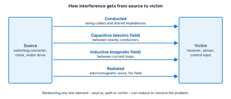
Interference only matters when it reaches a victim. The route it takes is the coupling path. Understanding the path tells you where to put a filter, a shield or a ground connection.
Four ways energy couples
| Path | Mechanism | Typical cause | Typical remedy |
|---|---|---|---|
| Conducted (galvanic / common impedance) | Noise current flows through a conductor or a shared impedance (a ground return, a supply rail) shared by source and victim | Switching current through a shared ground track | Separate returns, local decoupling, filtering |
| Capacitive (electric field) | A changing voltage (dV/dt) on one conductor drives a displacement current into a nearby one through stray capacitance | Fast-switching node next to a sensitive trace | Increase spacing, guard/shield, slow the edge |
| Inductive (magnetic field) | A changing current (dI/dt) in one loop induces a voltage in a nearby loop | Large current loop next to a sensor loop | Reduce loop areas, twist pairs, orient loops, magnetic shielding |
| Radiated (electromagnetic wave) | Energy leaves the source as a wave and is picked up by any conductor acting as an antenna | Cables and slots acting as unintended antennas | Reduce source currents, shield, filter at the cable |
In real products several paths act at once. A common sequence is: a noisy switching converter → common-mode current on the output cable → radiation from that cable.
Near field and far field
Close to a small source the electric and magnetic fields are not tied together as a wave. The boundary between the near and far field is roughly one sixth of a wavelength (λ/2π). At 30 MHz (λ ≈ 10 m) that is about 1.6 m; at 300 MHz (λ ≈ 1 m) about 0.16 m; at 1 GHz about 5 cm.
- In the near field of a low-impedance source (a loop carrying current) the magnetic field dominates; near a high-impedance source (a high-voltage node, a small antenna) the electric field dominates. Shielding that works against one may not work against the other.
- In the far field the wave has a fixed relationship between E and H (about 377 Ω in free space) and shielding theory is simpler.
This matters in testing: radiated-emission antennas at 3 m or 10 m measure far-field-like fields at higher frequencies, whereas near-field probes used in debugging measure local fields and cannot be compared directly to limits.
Differential mode and common mode
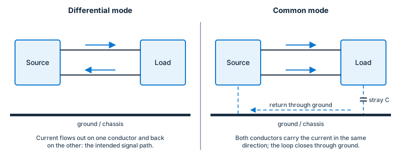
On a pair of conductors, noise current can flow in two ways:
- Differential mode (DM): the current goes out on one conductor and back on the other (for example line to neutral). It is the “wanted” signal path and usually dominates at lower frequencies. Because the currents are equal and opposite, the radiated fields largely cancel.
- Common mode (CM): the same-direction current flows on all conductors together and returns through ground, stray capacitance or the surrounding space. It dominates at higher frequencies and is the main cause of radiated emissions, because the currents add in the cable that then acts as an antenna.
Very small common-mode currents on a cable (of the order of microamps, depending on the frequency and cable length) can be enough to exceed radiated-emission limits. Differential-mode noise can convert into common-mode noise through asymmetry (unbalanced layout, unequal stray capacitances, shielding defects), which is why symmetric layout and balanced cables work well.
Why cables matter so much
A cable is an efficient antenna when its length is comparable with a fraction of the wavelength. A 1 m cable is a quarter- or half-wave resonator somewhere between roughly 75 MHz and 150 MHz, which is why many products show a radiated-emission peak in the 30–300 MHz region from their cables. Most EMC test methods therefore specify cable lengths and layout explicitly.
Spectrum of a digital signal
A repetitive digital signal has harmonics at multiples of its clock frequency. Roughly, the spectrum falls off slowly up to a “knee” frequency of about 0.35 / (rise time) (so a 1 ns edge has significant energy up to roughly 350 MHz), then falls off faster. Slowing edges, where function allows, lowers high-frequency emission. Spread-spectrum clocking spreads a peak over a wider band, which reduces the reading on the measurement detector but not the total energy.
Implications for design and testing
- Place filtering and shielding where a conductor crosses a boundary (a cable leaving an enclosure, a signal leaving a board).
- Think about return current paths: every signal current returns to its source, and the area of the loop sets both radiation and pick-up.
- Check CM currents on cables with a current probe: it is the quickest predictor of radiated-emission problems.
See also Design for EMC and Radiated emissions.
Further reading
- Henry W. Ott, Electromagnetic Compatibility Engineering (Wiley, 2009) and Clayton R. Paul, Introduction to Electromagnetic Compatibility (Wiley, 2nd ed., 2006): standard textbooks for the rules of thumb above.