Radiated emissions testing
How radiated emission tests work: antennas, distances, turntable and height scan, detectors, frequency range, test sites and common sources of failure.
A radiated emission test measures the unintentional electromagnetic energy a product radiates, so that it can be compared with a limit line designed to protect radio services.
The principle
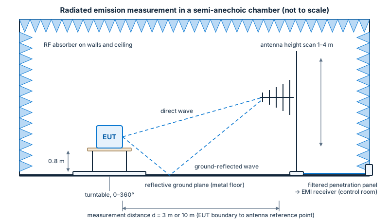
The product (the equipment under test, EUT) is operated in a defined, typical mode on a non-conductive table or floor-standing support, with its cables laid out as the standard prescribes. A calibrated antenna at a fixed distance picks up the field and an EMI receiver (or a spectrum analyser with suitable functions) measures it. Because the emission pattern is not uniform, the test maximises the reading:
- the EUT is rotated through 360° on a turntable;
- the antenna is moved in height (typically from 1 m to 4 m) for the open-site and semi-anechoic methods, because the ground reflection changes the field with height;
- both horizontal and vertical polarisation are measured.
The maximum value at each frequency is compared with the limit.
Distance, frequency range and detectors
- Distance: 3 m or 10 m between the EUT and the antenna in common commercial standards (30 m is also used for some equipment, and 1 m for some automotive component methods). Standards give limits for each distance; a 3 m limit is numerically higher than a 10 m limit because the field falls off with distance.
- Frequency range: typically starting at 30 MHz and going up to 1 GHz. Many standards extend the range upward depending on the highest internal frequency of the product (the multimedia standard CISPR 32 allows an upper frequency from 1 GHz to 6 GHz depending on that internal frequency).
- Detectors: emission limits are expressed for specific detectors. The quasi-peak detector (weighted by repetition rate, designed to reflect annoyance to broadcast listeners) is used below 1 GHz; peak and average detectors are used above 1 GHz. Measurement bandwidths are defined in CISPR 16-1-1 (for example 120 kHz for 30 MHz–1 GHz and 1 MHz above 1 GHz).
- Classes: Class A (commercial/industrial environment) and Class B (residential) limits; Class B limits are stricter (in CISPR 32 the radiated limits for Class B are 10 dB below Class A at the same distance).
The exact frequency range, limits and classes are given in the product standard (for example CISPR 32, CISPR 11, CISPR 14-1, CISPR 15 or FCC Part 15).
Antennas
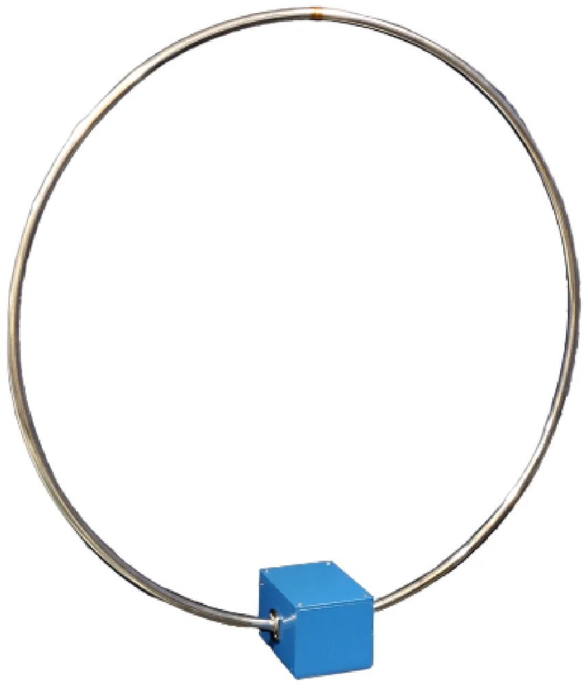
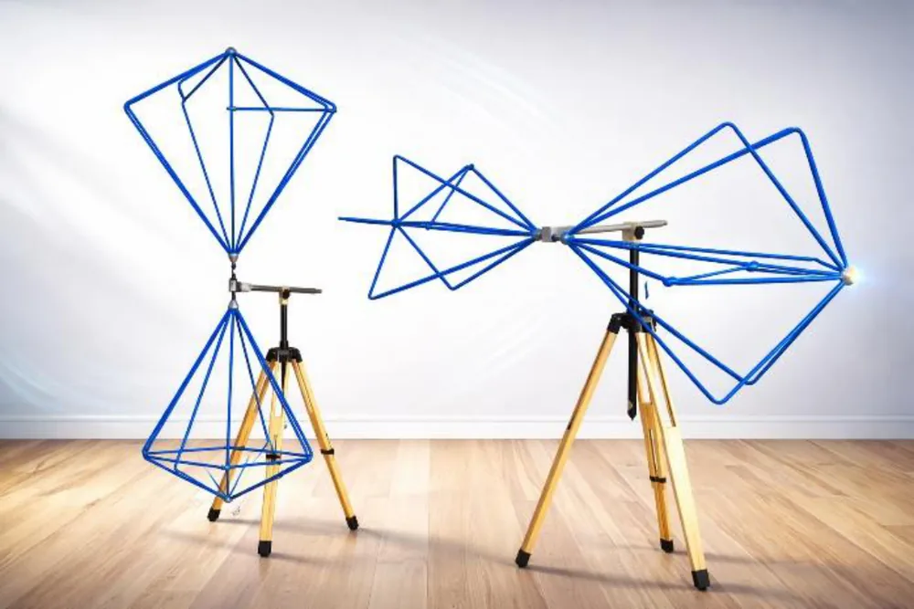
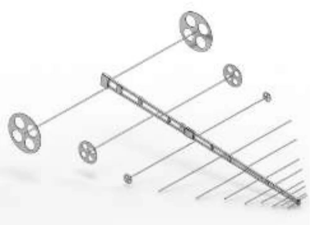
Common types are the biconical antenna (about 30–300 MHz), the log-periodic antenna (about 200 MHz to 1 GHz or higher), the combined biconical–log-periodic (“bilog”) antenna covering about 30 MHz to several GHz, and double-ridged horn antennas above 1 GHz. Antenna factors are calibrated, and CISPR 16-1-6 and 16-1-4 define calibration and suitability. Loop antennas measure the magnetic field below 30 MHz where the standard requires it.
Test sites
- Open-area test site (OATS): an outdoor site with a conductive ground plane, free of reflecting objects, which is the reference environment of the standards. It is affected by ambient radio signals and weather.
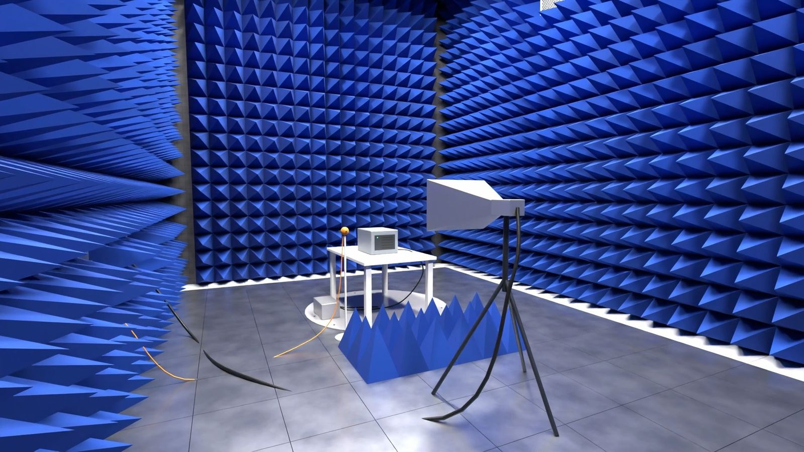
- Semi-anechoic chamber (SAC): an enclosed, shielded room lined with radio-frequency absorber on walls and ceiling with a conductive floor, reproducing the OATS indoors without ambient interference.
- Fully anechoic room (FAR): absorber on all six surfaces, used for methods above 1 GHz and some others.
Sites are validated against criteria such as normalised site attenuation (below 1 GHz) and site voltage standing-wave ratio (above 1 GHz). See Test facilities and site validation.
A typical procedure
- Setup: place the EUT, peripherals and cables per the standard; define operating modes that give the highest emissions.
- Pre-scan: a fast measurement with peak detection over the full range, at several turntable angles and both polarisations, to find candidate frequencies.
- Final measurement: at each candidate, maximise by moving the antenna height and rotating the turntable, then measure with the quasi-peak (or specified) detector.
- Evaluation: compare with the limit line; record the margin, the uncertainty and the configuration.
Measurement uncertainty is part of the evaluation: it is calculated per CISPR 16-4-2 and affects whether a result close to the limit can be declared compliant, depending on the standard’s rules.
Typical sources of failure
- Common-mode current on cables (power, I/O, USB, Ethernet, display cables);
- switching power supplies and DC–DC converters;
- fast clocks, memory buses and display interfaces;
- seams, slots and apertures in enclosures;
- motor drives and LED drivers.
Quick checks before the test: current-probe measurements on cables, near-field probes on the board, and tests in a simple pre-compliance setup. See Design for EMC.
Related methods
- Conducted emissions: Conducted emissions testing.
- Automotive component radiated emissions use a different, 1 m setup in an absorber-lined enclosure: Automotive EMC.