Conducted immunity testing (IEC 61000-4-6)
How immunity to radio-frequency conducted disturbances is tested: CDN, EM clamp and current injection, frequency range, levels and the 150 ohm reference.
At low radio frequencies the cables attached to a product are the most effective receiving antennas. A radio-frequency field of a few V/m induces a common-mode voltage and current on a cable that is long compared with the wavelength, and this disturbance enters the product through its ports. Conducted immunity testing injects that disturbance directly, rather than creating a field.
The principle (IEC 61000-4-6)
The method is described in IEC 61000-4-6 (European adoption: EN 61000-4-6):
- Frequency range: 150 kHz to 80 MHz. Above about 80 MHz a cable no longer acts as a simple receiving antenna coupling into the EUT in the same way, and the radiated-field method takes over. The standard allows an optional extension to higher frequencies where needed; product standards normally use the 150 kHz–80 MHz range.
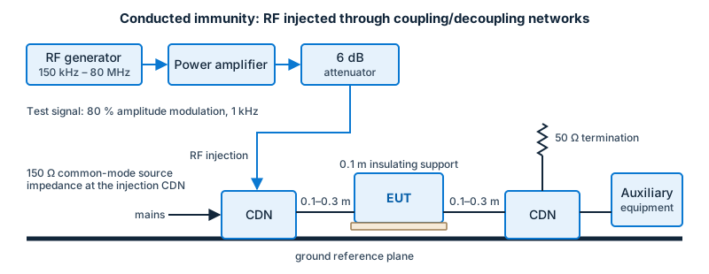
- Test levels: expressed as an unmodulated open-circuit voltage (“EMF”). Common levels are 1, 3 and 10 V, with the product standard defining which one applies. The test signal is amplitude-modulated (typically 80 % depth, 1 kHz) as in the radiated method.
- The 150 Ω reference: the disturbance source is specified with a 150 Ω common-mode source impedance, which represents typical cable and equipment impedances in the frequency range. Equipment, cables and calibration jigs are designed around this value.

Coupling and decoupling
The disturbance has to be put on the cable without upsetting the auxiliary equipment on the other end. The standard provides three ways:
- Coupling/decoupling network (CDN): a box through which the cable passes; it injects the disturbance on the EUT side and blocks it from the auxiliary equipment side. This is the preferred method.
- Electromagnetic (EM) clamp: a clamp with both capacitive and inductive coupling, used when no suitable CDN exists (for example for screened or multi-conductor cables).
- Current injection clamp: a clamp with an inductive coupling, used with a decoupling impedance on the auxiliary side; it is also used as a test method for larger cable harnesses (compare the automotive bulk current injection method).
A calibration step in a 150 Ω-to-50 Ω jig sets the generator output so that the correct level appears at the EUT port.
Procedure
The EUT is placed on an insulating support above a ground plane, and each cable port is tested in turn. The frequency is stepped (typically in 1 % steps) with a dwell time long enough for the EUT to react. Cable ports that are shorter than a given length (the standard sets a threshold) may be exempt.
Typical causes of failure
- unfiltered analogue sensor and audio inputs;
- ports with poor common-mode filtering, long unshielded cables;
- grounding structures that convert common-mode current to differential-mode voltage at the input.
Related automotive method
Automotive components use bulk current injection (BCI) per ISO 11452-4 with a similar principle but different levels (in milliamps) and a different frequency range; see Automotive EMC.